-
Scale the unsupported STL first, then re-orient and re-support at the new size—scaling pre-supported files is a common cause of failures.
-
Use uniform scaling to keep proportions; only scale individual axes when you’re intentionally changing the design.
-
Scaling changes the model’s weight and leverage, but your supports, layer height, and exposure/flow don’t auto-adjust—dial those in after resizing.
-
For parts that must fit, treat scaling as a dimensional accuracy problem: measure prints, account for first-layer effects and extrusion, then apply small compensation.
-
Don’t chase microscopic details that your printer can’t resolve—features smaller than your process limits won’t show up, no matter how perfect the STL is.
You’ve probably done it: you drop an STL into your slicer, bump it to 120% (or crush it to 85%), hit slice… and the print comes out “fine” but somehow wrong. Faces look softer, thin bits snap, sockets don’t fit, and suddenly that “quick scale” turns into a weekend of reprints.
Scaling is deceptively simple because the geometry scales instantly, while everything that actually makes a print succeed—supports, exposure/flow, shrinkage, first-layer behavior, minimum printable feature size—stays exactly where it was.
This guide walks you through how to scale STL models without ruining detail or fit, using the same approach I use for miniatures, props, and functional parts.
1. Know What Scaling Really Changes (And What It Doesn’t)
Scaling an STL applies a proportional multiplier to X/Y/Z dimensions. That’s it. The slicer doesn’t automatically “understand” that a 200% miniature now weighs a lot more, or that a 90% mechanical part now has thinner walls and tighter clearances.
What scales perfectly: The mesh geometry (every dimension scales by the same factor if you scale uniformly).
What does not automatically scale:
– Support strategy and support contact strength (critical for resin)
– Exposure settings (resin) or extrusion/flow behavior (FDM)
– Minimum feature limits (pixel size, nozzle width, layer height)
– Real-world dimensional error sources like shrinkage/thermal contraction
That’s why scaling can lead to soft-looking detail, weak supports, warped parts, or assemblies that don’t fit—even when the STL itself is “correct.”
2. Always Prefer Unsupported STLs (Scale First, Support Second)
If you take one rule from this article, make it this: scale the raw/unsupported model, then generate supports for the final size.
When you scale a pre-supported file, you’re scaling the supports too. That sounds convenient until you realize supports are not just geometry—they’re a tuned structure.
Scaling pre-supported STLs: When you increase the model size, the print gets heavier and creates more peel force, but your support tips and trunks may end up too thin for the new load. When you scale down, support tips can become so tiny they fail or don’t form properly.
Scaling unsupported STLs (recommended): You control orientation and can rebuild supports with the right thickness and contact points for the new size.
If you bought the model from a marketplace like Pixup3D (or other platforms that often include both versions), grab the unsupported file when you plan to resize.
3. Use Uniform Scaling Unless You’re Intentionally Redesigning
Uniform scaling keeps proportions intact. Non-uniform scaling (stretching one axis) is a redesign move—it can be useful, but it often causes “why does this look off?” results on characters and “why doesn’t this mate anymore?” problems on parts.
When uniform scaling is the right call:
– Miniatures (28mm to 32mm heroic, busts, display scales)
– Props and statues where proportions matter
– Any model with engineered relationships (pins, sockets, dovetails)
When non-uniform scaling can make sense:
– Compensating for a known machine bias in one axis (rare, and you should calibrate first)
– Adjusting ergonomics (e.g., making a handle thicker without changing length)
– Fixing a model that was designed with odd proportions
For most readers, if you’re asking “how do I scale without ruining detail or fit,” you want uniform scaling.
4. Detail Isn’t “Lost” in the STL—It’s Lost in Your Process Limits
A big misconception is that scaling “reduces STL resolution.” STL files store surfaces as triangles (tessellation). Scaling the mesh doesn’t magically delete triangles.
So why do details look worse sometimes?
Because your printer can only reproduce details above certain physical thresholds. If a texture ridge becomes smaller than what your printer can resolve, it will fade or vanish.
A practical rule of thumb from STL optimization guidance is that the smallest visible detail should be several times larger than your layer height (often cited as about 4× layer height). If you’re printing at 0.05 mm layers in resin, details smaller than ~0.2 mm are fighting physics. On FDM, nozzle width and line placement become the hard limit even faster.
What to do when scaling down:
– Accept that micro-textures may disappear
– Consider exaggerating details (a common sculpting-for-print approach)
– Use a smaller layer height where it actually helps (resin benefits more than FDM here)
What to do when scaling up:
– You’ll usually reveal more detail, but you may also reveal more layer stepping if you don’t keep layer height fine enough
5. Resin Miniatures: Rebuild Supports Like the Model Got Heavier (Because It Did)
Resin scaling problems are often support problems wearing a disguise.
When you scale a miniature up (say 150–200%), you increase:
– The part’s mass
– The cross-sectional area per layer
– Peel forces during separation
– Leverage on thin joints (weapons, ankles, capes)
Support changes after scaling up:
– Use thicker main supports and more of them under heavy islands
– Increase contact point size where it won’t scar visible surfaces
– Re-check islands after reorientation (don’t assume the old orientation is still optimal)
Support changes after scaling down:
– Avoid “hair-thin” support tips that won’t form reliably
– Reduce over-supporting tiny features (you can destroy detail during removal)
Layer height guidance for scaled minis: Even for larger minis, keeping a fine layer height (often 0.03–0.05 mm) helps preserve crisp textures and facial detail.
6. FDM Fit: Fix First-Layer and Extrusion Issues Before You Blame Scaling
If you scale a functional part and it doesn’t fit, your first instinct might be “I scaled wrong.” Many times, the real culprit is dimensional accuracy—especially on FDM.
Common accuracy factors include:
– First-layer nozzle distance affecting the bottom 10–20 layers (elephant’s foot and oversized bases)
– Under- or over-extrusion changing overall dimensions
– Thermal contraction/shrinkage, especially on larger parts or higher-temp materials
A measurement trick that saves time: Print a part tall enough (50–100 layers) and measure the top section rather than the bottom, so your numbers aren’t skewed by first-layer squish.
Calibrate extrusion/flow first:
– Too much flow can make parts oversized and holes undersized
– Too little flow can make parts undersized and weak
Once extrusion and first-layer behavior are under control, scaling becomes a predictable tool instead of a guessing game.
7. Decide If You Need “Scale” or “Compensation” (They’re Not the Same)
Scaling is a design-level change: “I want this 28mm mini to be 40mm,” or “I need this bracket to be 10% larger.”
Compensation is a manufacturing correction: “My printer makes holes 0.2 mm too small,” or “ABS shrinks about 0.5% on this geometry.”
Constant dimensional error: If your prints are consistently off by a fixed amount regardless of size (for example, always 0.1 mm too large), use a horizontal size compensation/XY offset style tool in your slicer when available.
Increasing dimensional error with larger parts: If the error grows with size, shrinkage/thermal contraction is a prime suspect. In that case, scaling by a small percentage (e.g., 100.5%) based on measured shrinkage can be more effective than a fixed offset.
A simple shrinkage calculation example:
– You print a 20 mm test and it’s 0.1 mm too small
– Shrinkage ≈ 0.1 / 20 = 0.5%
– Try scaling to 100.5% for that material/profile
This is also where a structured test approach (print, measure, adjust) beats intuition every time.
8. Treat “Fit” as a Tolerance Problem, Not a Vibe
If you’re scaling something that must assemble—armor panels, sockets, peg joints, threaded caps—your goal isn’t “looks right.” It’s “fits within tolerance.”
What changes when you scale down:
– Clearances shrink
– Walls get thinner
– Pins get weaker
What changes when you scale up:
– Clearances grow (sometimes too loose)
– Holes get bigger (but may still print undersized on FDM)
– Parts get heavier and may warp more (FDM) or need stronger supports (resin)
A workflow that works:
1. Scale the model.
2. Print a small test that includes the critical interface (a pin-and-socket slice, a corner with a dovetail, a short threaded section).
3. Measure with calipers and adjust with compensation (offset) or micro-scaling.
In research and industrial practice, dimensional accuracy is repeatedly shown to depend on multiple parameters and even the printer system itself—not just the STL. So if you change scale and also change orientation/support/hollowness, expect the fit to change too.
9. Check the Mesh and STL Export Quality Before You Resize Aggressively
Scaling can expose mesh problems you didn’t notice at the original size—holes, flipped normals, self-intersections, overlapping triangles. These issues can create slicing artifacts or weak areas.
Because STL surfaces are defined by triangle tessellation, export settings matter too. A coarse tessellation can make curves look faceted, and scaling up makes those facets more obvious.
What to look for before printing a scaled model:
– Watertight/manifold geometry (no open edges, no non-solid shells)
– No self-intersections
– No missing faces/holes
– Reasonable tessellation for curved surfaces
If you’re sculpting or editing, the classic “manifold rules” apply: avoid unwelded vertices, open holes, and intersecting faces that don’t form a clean volume.
10. Miniatures: Scaling Up for Display Without Making Them Look “Mushy”
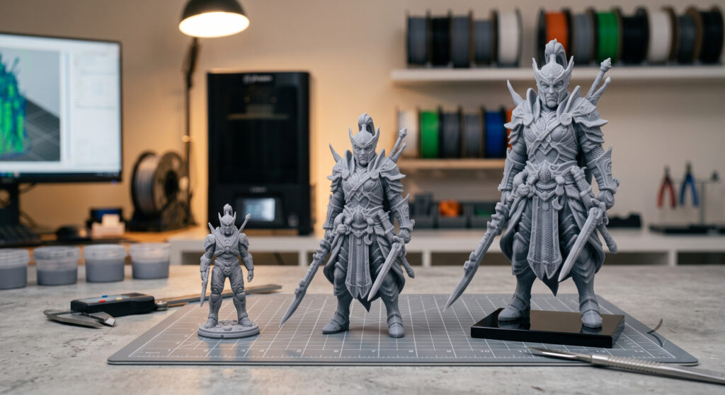
For tabletop-to-display scaling (common jumps are 150–200%), the STL usually holds up beautifully—your print settings are what decide whether it looks crisp.
Keep layer height fine enough: Scaling up makes surfaces larger and easier to inspect. If you keep the same layer height, you may see stepping more clearly on gentle curves. Resin printers (including options from Phrozen, Formlabs, and others) can keep that “miniature crispness” at larger sizes by staying in that 0.03–0.05 mm range.
Re-think fragile features: Spears, ankles, horns, and cape tips that were “just fine” at 32mm may become long, thin levers at 200%. Consider:
– Slightly thicker supports and stronger contact points
– Hollowing responsibly (if you hollow, plan drain holes and orientation)
– Reinforcement pins for extreme cases
Don’t over-wash away detail: When you’re chasing crispness, sloppy post-processing can undo it. Over-aggressive scrubbing on tiny textures or curing while resin is still pooled can soften edges.
Common Mistakes
Scaling pre-supported files and expecting the supports to still work
Pre-supports are tuned to a specific size, orientation, and weight. When you scale the whole scene, you change the mechanical reality of the print: heavier parts need thicker supports and better placement.
If you only have a pre-supported file, small scale tweaks might survive, but once you start making meaningful changes (like 150–200% display scaling), you’re gambling. Whenever possible, scale the unsupported STL, then rebuild supports for the new size.
Using scaling to “fix” dimensional accuracy problems
If your parts don’t fit, scaling everything up or down can feel like a fast fix—but it often masks the real issue: first-layer squish, extrusion multiplier errors, or shrinkage that grows with size.
Dial in first-layer behavior and flow/exposure first, then use compensation tools (offsets) or small percentage scaling based on measured error. You’ll get repeatable results instead of a one-off lucky print.
Scaling down and expecting tiny details to survive unchanged
When you shrink a model, you shrink every feature. At some point, textures and edges drop below what your printer can physically resolve (layer height, pixel size, nozzle width).
If you need a smaller version that still reads well, consider a version with exaggerated details (common in sculpting), a finer layer height (especially for resin), or simply choosing a model designed for that scale.
FAQ
Does scaling an STL reduce the file’s detail or “resolution”?
Scaling doesn’t inherently delete detail from the STL. What changes is whether your printer settings and hardware can reproduce the smaller features after resizing.
Should I scale in the slicer or in CAD/sculpting software?
For straightforward uniform scaling, the slicer is usually fine. If you need to preserve fit features (like standardized holes) while scaling everything else, CAD is better because you can selectively edit dimensions instead of scaling the whole mesh.
What’s the safest way to scale a resin miniature?
Use the unsupported STL, apply uniform scaling, then re-orient and regenerate supports sized for the new weight and peel forces. Keep layer height fine (often 0.03–0.05 mm) if you want crisp textures.
Why did my scaled FDM part come out oversized at the bottom?
First-layer nozzle height can cause extra squish that makes the bottom layers wider (elephant’s foot). Measure higher up the part to confirm, then correct first-layer settings and/or use elephant-foot compensation if your slicer supports it.
My holes never fit after scaling—what should I adjust?
On FDM, holes often print undersized due to extrusion and toolpath behavior. Calibrate flow/extrusion first, then use horizontal size compensation/XY expansion tools or adjust hole diameters in CAD for critical fits.
How much can I scale a pre-supported model before it fails?
There’s no universal safe percentage because it depends on the original support design and your resin/printer. Small tweaks might work, but for meaningful changes (especially scaling up), expect to rebuild supports.
If I scale up, do I need to change exposure (resin) or flow (FDM)?
Sometimes. Scaling up increases cross-sectional area and can change suction/peel behavior in resin, which may push you toward stronger supports or different orientation more than exposure changes. On FDM, scaling up can amplify shrinkage and warping, so material and cooling behavior may become more important.
What printers handle scaled detail well?
For resin miniatures and display prints, machines from Phrozen, Formlabs, and other modern MSLA/DLP options can capture fine surface textures when paired with appropriate layer height and supports. For functional FDM parts, accuracy depends heavily on calibration and material control as much as the printer brand.
Sources
- How to scale STL miniatures without losing detail
- [PDF] Analysis of the Effect of Scaling on Dimensional Accuracy of 3D …
- Dimensional Accuracy | Simplify3D Software
- Optimizing STL Files for 3D Printing | Dassault Systèmes
- Modeling for 3D Printing: Tips by Jeremy Ortiz – Formlabs
- Dimensional Accuracy of Different Three-Dimensional Printing Models as a Function of Varying the Printing Parameters
- 3D Printing Dimensional Accuracy: Definition & Tips to Achieve It – Raise3D: Reliable, Industrial Grade 3D Printer
- Choosing the Right Scale for Your 3D Printed Fantasy Models
- 3D Print Scale Models Without Losing Detail – Cura Tricks
- How to Scale STL Files Correctly for 3D Printing
Ready to put these ideas into practice? Browse 3D printable models on Pixup3D and find your next print!
If you're looking to get started with How to Scale STL Models Without Ruining Detail or Fit, here are some 3D printable models on Pixup3D that might inspire your next project: