

$ 0.00

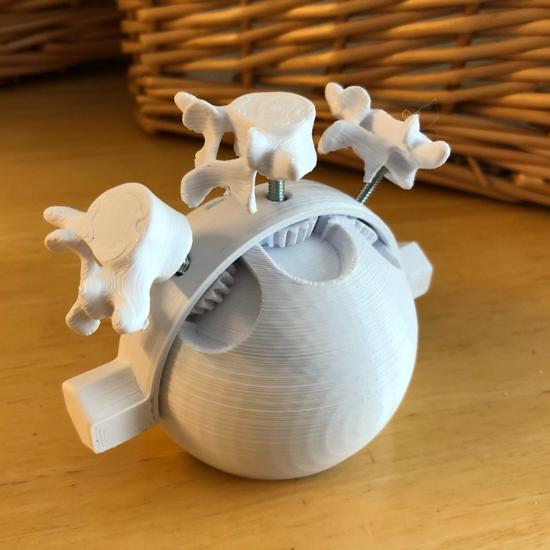
This teaching tool uses spherical cams to help visualize the coupled biomechanical movements that occur in the lumbar and thoracic spine during movement. See here for video and assembly sequence: https://youtu.be/jYGLIR5nwPY
“Fryette’s Laws” are a set of guiding principles used by physiotherapists and practitioners of osteopathic medicine to discriminate between dysfunctions in the axial skeleton. The coupled movements can be tricky to visualize, and especially difficult to explain to patients.
In this model, the central vertebrae represents the spine in neutral and demonstrates the first principle:
“Principle I: When the spine is in neutral, sidebending to one side will be accompanied by horizontal rotation to the opposite side.”
The front and back vertebrae represent the spine in flexion and extension respectively. These vertebrae demonstrate the second principle:
“Principle II: When the spine is in a flexed or extended position (non-neutral), sidebending to one side will be accompanied by rotation to the same side.”
See here for more details on Fryette’s Laws: https://en.wikipedia.org/wiki/Fryette%27s_laws
Printing
Print three “Gear” files and one of each of the remaining files. You'll need three 1/8" fine thread bolts, 3/4" in length. Refer to the video for assembly instructions, paying particular attention to proper orientation of the base. For the slots that hold the front and back vertebrae, the teeth should be on the back edge of the slot. For the slot that holds the central vertebrae, the teeth should be on the front edge of the slot.
See here for another spherical cam project: https://www.thingiverse.com/thing:4884439


